2.1 THE MAJOR ROCKET ENGINE DESIGN PARAMETERS
To fit the engine system properly into a vehicle system, engine systems design and development specifications will have to cover the following parameters above all: (1) Thrust level (2) Performance (specific impulse) (3) Run duration (4) Propellant mixture ratio (5) Weight of engine system at burnout (6) Envelope (size) (7) Reliability (8) Cost (9) Availability (time table-schedule)
As the design progresses, numerous additional parameters will have to be considered. Before turning to the latter, let us briefly review and discuss those listed above. It should be noted that the last five items are closely interdependent. For instance, making an engine available in the shortest possible time ("crash program") will raise the cost and will unfavorably affect reliability. A longer design and development period may not necessarily reduce cost, but it will offer higher values in exchange for the dollar; higher reliability, refined (lower) weight, and an optimized (smaller) envelope.
Thrust Level
This engine parameter is a basic one, similar to the power rating of a gasoline engine or electric motor. It will affect most of the other engine parameters and many of the development considerations.
The total thrust requirement of a rocketpropelled vehicle is predominantly governed by-
- The total takeoff weight of the vehicle (including engine!)
- Minimum and maximum accelerations permissible Selection of the proper engine thrust level results from the decision whether a single- or a multiple-engine system is to be used. This decision is often strongly influenced by the availability of already existing engines, which would eliminate, or at least drastically reduce, the design and development cost for the propulsion system. The selection of individual engine thrust level also is-or at least should beinfluenced by the general state of the art, particularly if sizes substantially larger than previously developed are considered.
More recently, largely as a result of the advent of manned rocket night and of the high cost of very large vehicle systems, the decision to use a multiple (clustered) propulsion system consisting of several engines rather than a single one has been additionally affected by safety considerations, to permit mission completion, or at least safe return of the crew, in case of an engine failure. This "engine out" principle is analogous to the consideration of multipleversus single-engine airplanes. Extensive studies have been conducted in this field for rocket vehicles to establish the "break-even" point regarding the minimum and maximum number of engines profitably employed in a cluster. Failure of single-engined rocket vehicles not only might destroy the vehicles themselves but also could cause severe damage to expensive ground facilities. This explains the great emphasis placed on thrust subdivision.
Thrust levels for first-stage booster engines, which start at or near sea-level altitude and stop at a specified higher altitude, are usually quoted for sea-level conditions. Additionally, the specifications may contain information on thrust level at altitudes above sea level, frequently in the form of a graph (see fig. 2-1).
The nominal thrust of engines in stages starting and operating at or near-vacuum conditions is quoted for that environment. Most engines are designed for a single nominal thrust (sea level or altitude), for which they are calibrated by
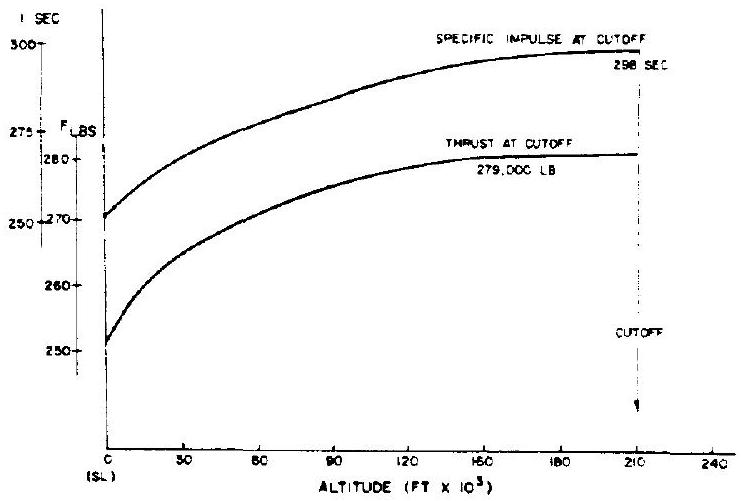 Figure 2-1.-Typical graph of rocket engine performance as function of altitude.
means of propellant line orifices or, less frequently, with the aid of regulators. Engines designed for variable thrust (throttling) always require some type of regulator. This will be discussed in section 7.3, "Engine Thrust Level Control."
Performance
Although the general term "performance" of a rocket engine in the strict sense covers a number of parameters ( , etc.), specific impulse ( ) is considered the prime performance parameter. As was seen in chapter I, the specific impulse, also referred to as specific thrust, is measured in seconds, which obviously is not the dimension of time, but an abbreviation of the dimension lb -sec (specific impulse), sec) (specific thrust), respectively. It is important to state whether a specified value of refers to the complete engine system, or to the thrust chamber only. Frequently, by stating a percentage an "actual" or "practical" value of is linked to the maximum value theoretically possible. The theoretical values for the better known propellant combinations are well established and as a result practical values have become quite predictable. With less well-known combinations, disappointments have often resulted. Therefore, great caution is advisable in the use of theoretical values which have not been verified in an actual test.
In recent years, the performance of a rocket engine, as expressed by its specific impulse, has received considerable attention, far beyond its true significance. In June 1959, Dr. von Kármán observed:
It is my personal belief that the length of the period of anaining reasonable reliability in the development process could be essentially reduced if simple design were emphasized as a leading principle, even if we had to make some sacrifice in the quantitative measure of "efficiency." Essential elements have to be designed as simply as possible, even if this means a reduction in quantitative efficiency and a certain increase of bulkiness and or weight.
Undoubtedly, these observations were prompted by a noticeable trend on the part of both the engine builder as well as the customer, to sacrifice, or at least to compromise, nearly all other capabilities of a rocket propulsion system for increases, which sometimes amounted to less than 1 percent.
Frequently, increasing emphasis on during the life of a project can be traced to marginal engineering reserves in the initial vehicle design especially with weight assumptions and tank capacities. The need for competitive bidding may have contributed to this situation.
On the other hand, the highest which can be obtained without compromise will pay off substantially. For instance, in the case of a typical medium-range ballistic missile, an increase of 1 second in will effect a range increase of approximately 15 nautical miles. In other terms, an increase of less than one-half percent results in a range increase of 1 percent. As impressive as these figures for increased flight range are, it should be kept in mind that those engine properties which will determine whether the vehicle will fly at all should not be com-
Duration
Because, by definition, a rocket vehicle carries its own complete propellant supply, including the oxidizer, its run duration is limited, as a result of an optimized balance between takeoff weight, trajectory, thrust level, and minimum and maximum accelerations. Consequently, run-duration times of most large liquid-propellant rocket engines fall into a relatively narrow band, about 50 to 400 seconds.
User specifications include a formal demonstration (such as preliminary flight rating tests (PFRT) and qualification tests) requiring accumulated duration times, without breakdown, of many times the comparatively short rated flight duration (typical: six full duration tests for PFRT of an ICBM).
These specifications, therefore, govern most engine design considerations, with the exception of the following areas, which for weight considerations are tailored to the flight-run duration: (1) Auxiliary tank capacity, for systems which employ a separate turbine power supply (2) Propellant-tank pressurization supply, if it is part of the engine system (3) Lube oil tank capacity, if applicable (4) Temperature nonequilibria, such as those of uncooled nozzles
Closely related to the run duration are the start and shutdown characteristics of an engine system, the requirements for both of which may be very stringent in a given vehicle system.
The characteristics and the quality of the "start," or "thrust buildup," of a liquid rocket engine are judged by- (1) Compliance with specified thrust versus time characteristics (2) Maximum rate of increase at any time during buildup (3) Freedom from surges and thrust overshoots (4) Smoothness (freedom from damaging oscillations) (5) Repeatability from run to run and from engine to engine These characteristics will be discussed in greater detail in chapter X, "Engine Systems Design Integration." Suffice it to state, at this point that a rocket engine is not easy to adapt with special thrust buildup requirements. Difficulties in this area can arise from inadequate communication between the vehicle contractor and the engine contractor. Thorough understanding of the problems by both contractors is vital.
The characteristics of engine "shutdown" or "thrust decay" are predominantly influenced by guidance considerations. To understand this better, let us consider the case of a single-stage, ground-to-ground, ballistic missile. As the term "ballistic" implies, the missile is designed to impart a desired speed to a known payload, in a desired direction from a desired point, after which the payload coasts freely to the target.
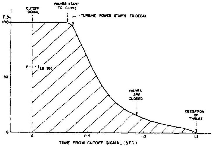 Figure 2-2.-Typical thrust decay diagram.
This is analogous to a cannon, where muzzle exit velocity of the projectile, gun-barrel attitude, and location of the gun emplacement will determine the point of impact (neglecting environmental influences such as wind). With a ballistic rocket, the gun barrel is literally replaced by the guidance system, the intricate components of which not only predetermine the three basic parameters mentioned but also have the capability to compensate for deviations of any or all of them. If, for instance, the trajectory angle near the point of cutoff is too steep, the guidance system will compensate accordingly, by calling for a higher final velocity, by slightly delaying the cutoff signal, simultaneously considering the distance over ground already covered.
It is obvious that a prompt and repeatable execution of the cutoff signal is imperative. However, for several reasons, it is impossible to effect a truly instantaneous thrust cessation: time is required to sense and then transmit the cutoff signal; closing of valves requires a finite time; structural (hydraulic hammer) considerations are superimposed; residual propellants below the valves have an effect. Figure 2-2 shows a typical thrust decay diagram.
Let us recall:
Thrust multiplied by time equals mass times velocity increase, or
The velocity increase following cutoff signal is a function of the residual thrust acting on the vehicle mass , and is integrated over the time from cutoff signal to final thrust cessation; this integral is commonly referred to as the "cutoff impulse." A typical value for a well-known earlier rocket (Redstone) was . Note the tolerance. This deviation will obviously influence missile accuracy. Reduction of the tolerance is thus an important design and development goal.
It might be concluded that a substantial reduction of the tolerance is the principal task, zero deviation being the optimum. This is unfortunately not so because the final vehicle mass , on which the decaying thrust force acts, is unpredictable within certain limits, due to weighing tolerances of the initial vehicle mass, and to flow rate and mixture ratio tolerances. The engine designer and developer will have to concentrate on reducing both: base value and tolerance.
A glance at figure shows that the area under the thrust curve is a function of not only decay time but also of main-stage thrust level. In fact, the major portion of the shaded area is accumulated prior to the beginning of thrust decay. This observation has led to the utilization of vernier thrust systems.
A vernier cutoff system is characterized by a substantial thrust reduction before final cutoff. This can be accomplished by thrust reduction, for a few seconds, of the main engine itself (V-2 fashion) or by shutdown of the main engines. while much smaller engines continue for a brief period (typical: seconds, depending on final required).
It should be emphasized that any components that must be added to improve cutoff characteristics are basically undesirable, since engine complexity is drastically increased. The addition of such components should be avoided at all costs. Here again, close coordination between the vehicle (guidance) designer and engine designer, and thorough understanding of their common problems, is vital.
Mixture Ratio
As is well known, complete combustion of a given amount of fuel requires a corresponding amount of oxidizer. That mixture ratio which effects complete combustion, with no leftover of either fuel or oxidizer, is called the stoichiometric mixture ratio. This ratio depends on the type of propellants used. Theoretical temperature and heat release are maximum at this ratio. In rocket engines, however, where the highest possible exhaust velocity is desired, optimum conditions often prevail at other than stoichiometric ratios. Equation 1-18 indicates that the gas properties strongly affect exhaust velocity. The expression for the specific gas constant, , in equation 1-18 may be rewritten as-
where is the universal gas constant and is the molecular weight of the gas (see table 1-1).
The lower the molecular weight, the higher the exhaust velocity, other things being equal. Analytical and experimental investigations will determine the optimum point of balance between energy release (heat) and composition (molecular weight) of the gas, a portion of which will consist of gasified but unburnt propellants. The optimum point may also be affected by- (1) Stay time of the burning gas in the combustion chamber.-Stay time is a function of combustion chamber volume and of gas volumetric flow rate. Complete combustion, even though desirable, requires a finite time which is not available unless the chamber is relatively large, and correspondingly heavy. A compromise in chamber size, therefore, is often made. This leaves unburned a small percentage even of those propellants entering the nozzle, which could have burned given sufficient time (chamber volume). This percentage must be considered for accurate determination and optimization of the composition of the combustion gases and when optimizing the gas properties with energy release and system weight. (2) Cooling considerations.-The temperatures resulting from stoichiometric or nearstoichiometric mixture ratios, dependent on propellant type, may impose severe demands on the chamber-wall cooling system. A lower temperature, therefore, may be desired and obtained by selecting a suitable ratio. Once the optimum mixture ratio has been determined for a given engine system, based on the major factors just discussed, it is obvious that deviations from it would result in engine performance penalties. Since the vehicle powered by an engine will have been sized and tanked to conform with the specified engine mixture ratio, it is important to know that deviations will also result in reduced vehicle performance, namely: (1) Reduced engine duration, due to premature exhaustion of one of the propellants (2) Reduced mass ratio, due to excessive residual amounts of the other propellant (increased burnout weight) Since the relationship between engine performance ( ) and mixture ratio for many systems is usually relatively flat near the optimum point (fig. 2-3), the effects from duration and burnout weight may well be the most influential ones for vehicle range.
The effects of even minor discrepancies in mixture ratio (propellant utilization) are substantial. For instance, in a typical single-stage medium-range ballistic missile, each pound of excess burnout weight will result in a range decrease of approximately 0.2 nautical miles. For long-range vehicles, the penalty is still higher. The close target tolerances that have occasionally been reported for test flights illustrate the remarkable degree of accuracy which can be achieved from all contributing subsystems.
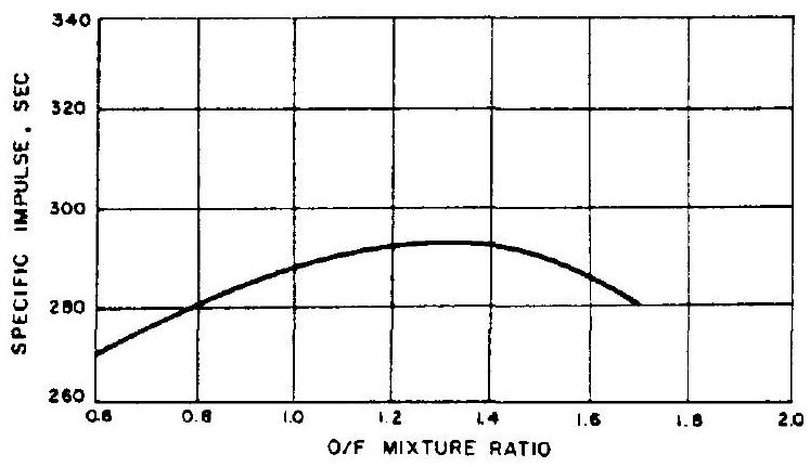 Figure 2-3.-Theoretical thrust chamber performance vs mixture ratio for at shifting equilibrium and optimum sea level expansion.
Weight
The parameter of weight, as no other, dominates the thinking of those employed in rocketry. Weight of payload flown over a distance, or placed into orbit, is the ultimate accomplishment. Success is often gaged directly in pounds of payload flown per dollar spent.
The importance weight rightfully carries does not necessarily mean that it is all important. For instance, a somewhat smaller payload placed into orbit more reliably, or at a lower cost per pound, may be preferred. By and large however, weight is a most important consideration.
As we have seen earlier, a vehicle's final velocity is a function of, among other parameters, its mass ratio. The smaller the final mass, the higher the final velocity. However, since payload mass should be as high as possible, the weight squeeze is applied to all those vehicle components which are not payload. This includes the engine.
To isolate the influence of vehicle-structures weight, a parameter called "propellant fraction" has come into increased usage. This factor expresses the ratio of the total propellant weight to the fueled vehicle weight without payload. Typical values are 0.94 for turbopump-fed systems, and 0.89 for pressure-fed systems. For turbopump-fed engines, the ratio of thrust to engine weight is a useful additional yardstick. Larger modern liquid rocket engines may fall into a range from 75 to 125 pounds of thrust 1 b of engine weight. These figures represent a substantial progress over the past (see fig. 2-4).
As was seen with residual propellants, excessive dead weight at burnout imposes penalties. Therefore, whenever rocket engines can be made lighter without compromising reliability and structural integrity, the payoff in range and payload will be sizable.
Engine and vehicle builders usually distinguish several types of engine weight: (1) Dry weight.-The net weight of the engine as it leaves the factory. (2) Burnout weight.-The engine dry weight plus residual, measurable propellants remaining in the engine at cutoff. In a typical engine design, burnout weight may be 4 percent higher than dry weight. Burnout weight is significant for vehicle mass ratios (eq. 1-30).
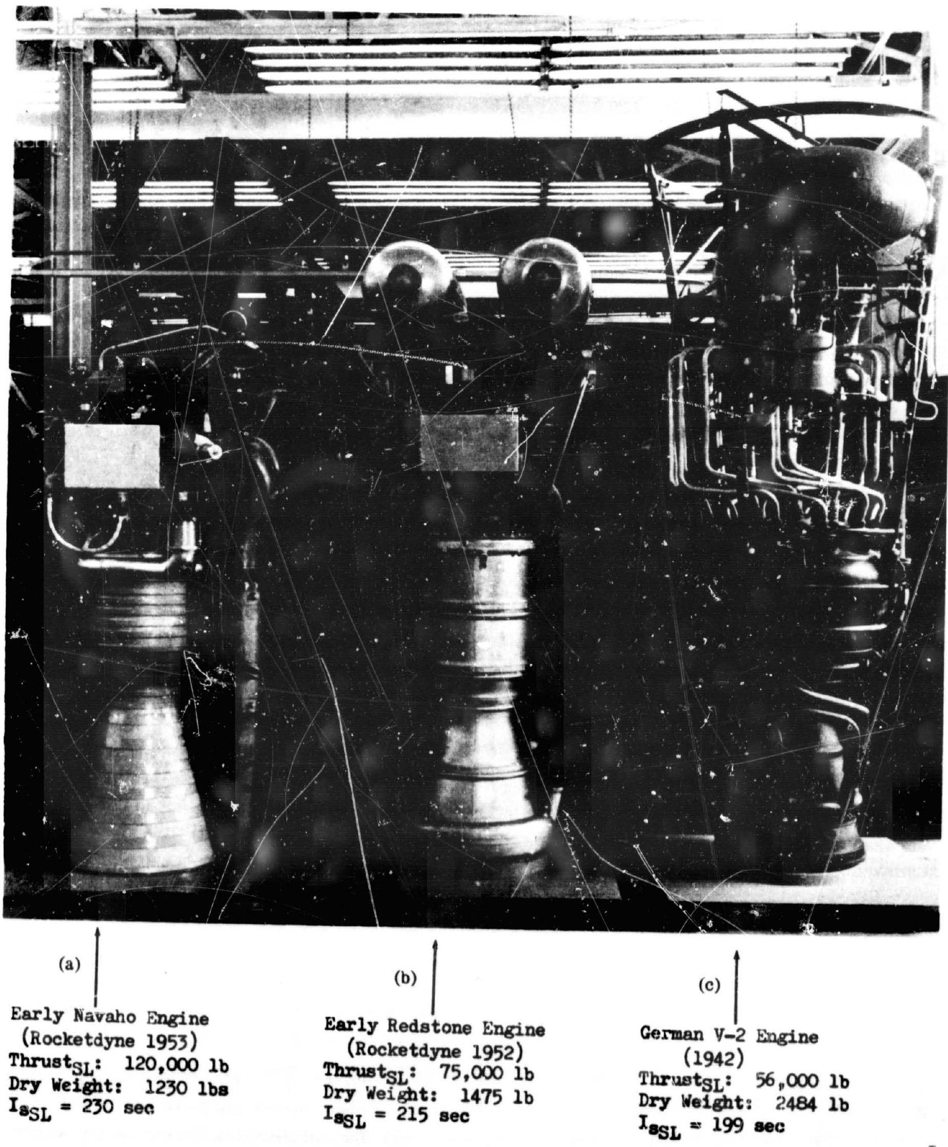 Figure 2-4.-Substantial progress has been made in ratio of thrust to engine weight.
(3) Wet weight.-The engine dry weight plus all propellant within it, during main stage. In a typical design, engine wet weight may be 6 percent higher than dry weight. Wet weight is significant for vehicle in-flight center-of-gravity location and moments of inertia. (4) Wet gimbaled weight.-That portion of wet weight representing engine mass which is gimbaled for steering purposes. In earlier designs this meant essentially the thrust chamber and injector wet weight. In later designs it often refers to the entire engine less a relatively small amount of stationary parts. This weight is significant for gimbal actuator loads and guidance control loop response characteristics.
Ideally, dry weight and burnout weight should be equal; that is, no propellants should be trapped in the engine at shutdown. In practice, this will not always be possible. However, the engine designer can do much through proper design, siz- ing and routing of lines, avoidance of traps, and location of valves.
Because of the importance of weight control, rocket engine manufacturers employ engineers specifically in charge of this area. Table 2-1 shows a typical weight progress form, as it is used by the Rocketdyne Division of North Amercan Aviation. It is revised and reissued periodically. Thus it becomes a useful tool to raise early danger warnings. In our arbitrary example a slight underweight is shown. However, the table also shows that the data are based almost entirely on estimated and calculated figures, rather than on actual weighing results. This is characteristic for the earlier phases of design and development of a rocket engine. More often than not, the weight advantage will disappear gradually as the design firms up; then the squeeze will be on. For convenient display of the weight tendencies over time, a graph such as shown in figure will be useful.
The weight changes of the various components as well as of the entire engine affect centers of gravity and moments of inertia. Through
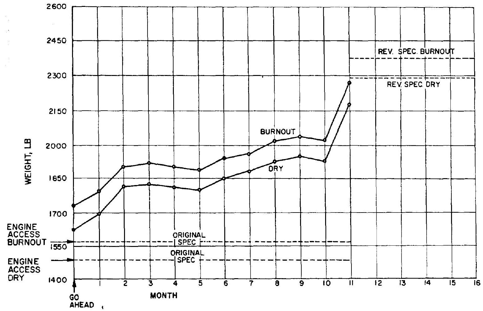 Figure 2-5.-A-2 stage rocket engine and accessory weight history.
Table 2-1.-A-2 Stage Engine Weight Report
| Model: A-2 stage Contract: Issue: 1 Date: Feb. 28. 1964 Enclosure: Page: 1 Report No. 12 | Contractor changes (rev spec. weight) | Current status | Last status (Report No. 11) | Changes last to current status (col. 4 minus col. 5) | Basis for current data | Notes | |||
|---|---|---|---|---|---|---|---|---|---|
| Spec weight per original design | Percent, estimated | Percent. calculated | Percent, actual | ||||||
| 1 | 2 | 3 | 4 | 5 | 6 | 7 | 8 | 9 | 10 |
| Rocket engine and accessories (at burnout) (A+D+E) | (1580) | (2380) | (2292) | (2112) | (+180) | ||||
| Rocket engine and accessories (dry) (B+D) | (1485) | (2280) | (2181) | (2011) | (+170) | (30) | (52) | (18) | |
| A Rocket engine (at burnout) (BlC) | (1365) | (2000) | (1923) | (1763) | (+160) | ||||
| B Rocket engine (dry) | (1300) | (1930) | (1850) | (1700) | (+150) | (24) | (59) | (17) | |
| Thrust chamber | 500 | 750 | 730 | 640 | +90 | 7 | 62 | 31 | |
| Gimbal bearing | 40 | 55 | 52 | 6 | 94 | 0 | |||
| Turbopump. fuel | 200 | 260 | 250 | 217 | +33 | 1 | 97 | 2 | |
| Mount, fuel pump | 25 | 30 | 7 | 1 | 87 | 12 | |||
| Turbopump, oxidizer | 190 | 230 | 224 | 202 | +22 | 0 | 33 | 67 | |
| Mount. oxidizer pump | 25 | 30 | 28 | 26 | +2 | 3 | 82 | 15 | |
| Fuel feed system | 70 | 100 | 95 | 96 | +1 | 72 | 28 | 0 | |
| Oxidizer feed system | 60 | 90 | 87 | 87 | 0 | 75 | 25 | 0 | |
| Controls (ignit. elect. pneu.) | 100 | 130 | 114 | 114 | 0 | 65 | 33 | 2 | |
| Exhaust system | 70 | 100 | 96 | 96 | 0 | 60 | 39 | 1 | |
| Propellant utilization system | 10 | 15 | 12 | 10 | +2 | 4 | 96 | 0 | |
| Start system | 0 | 140 | 135 |  | 0 | 100 | 0 | 0 | |
| C; Flud at burnout (rocket engine) | (65) | (70) | (73) | (63) | (+10) | ||||
| D Accessories | (185) | (350) | (331) | (311) | (+20) | (57) | (41) | (2) | |
| Inlet line, fuel pump | 50 | 85 | 79 | 74 | +5 | 33 | 65 | 2 | |
| Inlet line, oxidizer pump | 50 | 85 | 81 | 75 | 16 | 30 | 64 | 6 | |
| Helium bottle | 0 | 24 | 21 | 21 | 0 | 100 | 0 | 0 | |
| Heat exchanger, oxygen | 30 | 34 | 31 | 27 | +4 | 12 | 82 | 6 | |
| Flowmeters | 5 | 6 | 5 | 5 | 0 | 100 | 0 | 0 | |
| Instrumentation | 50 | 80 | 78 | 73 | +5 | 100 | 0 | 0 | |
| Vehicle connection provision | 0 | 36 | 36 | 36 | 0 | 100 | 0 | 0 | |
| E Fluid at burnout (accessories) | (30) | (30) | (38) | (38) | (0) |
| A-2 STAGE ROCKET ENGINE | |||||||
|---|---|---|---|---|---|---|---|
| CENTER OF GRAVITY AND MOMENT OF INERTIA DATA | |||||||
| ENCLOSURE DATE Eebruary 28, 1964 PAGE | |||||||
| DESCRIPTION | WEIGHT LBS. | CENTER OF GRAVITY - INCHES | MOMENT OF INERTIA - SLUG FT | ||||
| Y - ARM | X - ARM | Z-ARM | Y - Y | Z-Z | |||
| (1) Rocket Engine - Acc. - Dry | 2181 | . 23.3 | -1.5 | 0.7 | 176 | 391 | 362 |
| (2) Rocket Engine + Acc. - Wet | 2317 | -22.5 | . 15 | . 01 | 185 | 411 | 379 |
| (3) Rocket Engine. Acc. - Burnout | 2292 | . 227 | . 16 | -0.2 | 184 | 408 | 375 |
| (4) Gimballed Mass - Dry | 2061 | +25.2 | . 15 | 0.2 | 672 | 849 | |
| (5) Gimballed Mass - Wet | 2086 | -24.6 | 1.5 | -0.2 | 177 | 688 | 662 |
Figure 2-6.-Typical data sheet for center of gravity and moment of inertia.
issue of a data sheet as shown in figure 2-6, all parties concerned can be kept informed on changes as they occur.
Note that the data presented in table 2-1 and figures 2-5 and 2-6 are for the 150 K A-2 stage engine system which is a part of an assumed multistage space vehicle configuration treated in later chapters.
Let us now explore the influence structural weight has on the performance and gross takeoff weight of a rocket vehicle system, and how its magnitude varies with the design parameters of different vehicle systems. The quantitative relationships will be evaluated individually for each case.
Equation (1-30) can be rewritten for the stage burnout velocity of a single-stage vehicle, or the stage velocity increment, of any individual stage of a multistage vehicle system as:
where
Stage structure,
\begin{gather*} \text { Stage engine } \tag{2-2}\\ \text { system weight } \end{gathered}+\begin{gathered} \text { guidance and other } \\ \text { weights, which are } \\ \text { not payload } \end{gather*}It can be concluded from these equations that for a given burnout velocity, there is an even weight trade off between stage engine system weight and stage payload weight. If the weight of all other items were kept constant, a pound decrease in the stage engine system weight will increase the stage payload capacity by 1 pound.
For a fixed payload, and assuming other items except engine weight to be constant, the relation between the stage velocity increment, , and stage engine system weight for a given system can be written as (2-3) where constant
Stage usable propellant weight constant Since , the denominator will decrease more rapidly than the numerator, with decreasing engine weight. Thus for fixed payloads, an increase in burnout velocity is realized which will pay off in longer range or higher orbit.
For a given burnout velocity and for a fixed pavload, the required stage average overall specific impulse ( in terms of stage engine system weight can be established as
where
Equation (2-4) shows that with decreasing engine-system weight, the overall specific impulse requirements decrease.
Another parameter illustrating the importance of weight is the growth factor of a rocket vehicle system. For instance, if the weight of a component increases, it is possible to adjust for this by increasing the weight of the propellants loaded and thus possibly that of other components, such as a pump, to maintain the same required vehicle performance; i.e., payload and vehicle trajectory. Therefore, if one part of the vehicle system exceeds its weight allotment by 1 pound, an increase of the total vehicle system weight at takeoff by a certain number of additional pounds will result. Growth factor is defined as the total vehicle system (including payload) weight increase at takeoff, divided by the causal increment of added inert and/or payload weight. It is emphasized that the growth factor, for a given vehicle system, is not a precise value, but varies within a band. For instance, a small weight increase of a component in an existing system may only require the addition of a corresponding small amount of propellants, but not require enlargement of the tanks, valves, etc. Accordingly, the growth factor will be small. In another case, the weight increase may be "the straw that breaks the camel's back," requiring the use of the next larger valve size, duct size, or the like. The growth factor will then be large.
In general, however, the growth factor of a vehicle system is a useful tool during the preliminary design of an engine system, because it attaches a tangible value to the importance of the engine-system weight. A systems weight increase may be considered "uninvited payload." For single-stage vehicles, and relatively small weight changes, the value of the growth factor then can be expressed with sufficient accuracy as
For any stage of a multistage vehicle, the approximate value of the growth factors against total vehicle system weight at takeoff can be expressed as
The growth factors of any stage against the vehicle system weight at ignition of the same or lower stage can be expressed as
Sample Calculation (2-1)
A three-stage rocket vehicle system has the following weight data: Total vehicle system weight at takeoff, 40000 pounds. Vehicle system weight at second-stage ignition, 7500 pounds; vehicle system at third-stage ignition, 2200 pounds; payload weight, 700 pounds. For each pound increase of engine system weight of first, second, and third stages, respectively, determine (at a constant vehicle performance): (a) increases of total vehicle system weight at takeoff; (b) increases of vehicle system weight at second- and third-stage ignition.
Solution
(a) Payload weight of first stage = vehicle system weight at second-stage ignition = 7500 pounds Payload weight of second stage vehicle system weight at third stage ignition 2200 pounds Payload weight of third stage = actual system payload weight pounds From equation (2-6): (1) Growth factor of first stage against vehicle system takeoff weight = (2) Growth factor of second stage against vehicle system takeoff weight = (3) Growth factor of third stage against vehicle system takeoff weight =
Therefore:
For each pound increase of first-stage enginesystem weight, the increase on vehicle system takeoff weight pounds For each pound increase of second-stage engine-system weight, the increase on vehicle system takeoff weight pounds
For each pound increase of third-stage enginesystem weight, the increase on vehicle system takeoff weight pounds (b) Note that the weight growth of lower stages will not affect the upper stage weight growth. For an increase of first-stage vehicle system weight, there will be no weight changes on second and third stages, and for an increase on second-stage vehicle system weight, no weight change is required for third stage.
From equation (2-7): (1) Growth factor of second stage against vehicle system weight at second-stage ignition =
Vehicle system weight (2) Growth factor of third stage against vehicle system weight at second-stage ignition =
Vehicle system weight (3) Growth factor of third stage against vehicle system weight at third-stage ignition =
Therefore: For each pound increase of second-stage engine system weight, the increase on vehicle system weight at second-stage ignition pounds For each pound increase of third-stage engine system weight, the increase on vehicle system weight at second-stage ignition pounds, and the increase on vehicle system weight at third-stage ignition pounds The correctness of results can be checked by recombining the individual stage growth factors to obtain the growth factor for the entire vehicle system:
Envelope (Size)
The linear dimensions of liquid propellant rocket engines require relatively elaborate description and frequently cannot be made clear without a drawing. In those cases where only approximate values are required for comparison or for overall estimates, the term "envelope" is preferred. For instance, definition of a hypothetical smallest cylinder, cube, or sphere into which the engine would fit conveys a good feeling of engine size or bulkiness.
Obviously, engine size directly affects engine weight, the importance of which was emphasized above (fig. 2-4). Aside from the engine itself, numerous other areas are directly affected by increasing engine size: (1) The vehicle structure, which becomes heavier, especially with upper stages. Engine size directly affects the size and thus weight of the aft end and/or interstage structure. (2) Handling equipment and procedures become more costly (3) Servicing becomes more difficult (4) Manufacturing machinery becomes larger (5) Storage and transportation means become more bulky In several of these areas, there is a definite upper limit, such as railroad tunnel sizes, clearances on bridges and underpasses, and available machine tools.
The selection of the thrust-chamber expansionarea ratio has a very pronounced effect on engine envelope. When optimizing the thrust chamber expansion area ratio, which is also influenced by performance, weight, pressure drop, heat transfer, and other considerations, its effect on envelope, and thus on other vehicle systems, must be considered (section 10.9).
Reliability
The subject of reliability has become almost a branch of science by itself. In addition to the designer, to the development engineer, and to the user, mathematicians, statisticians, and "human factor" and "man rating" specialists are involved. Numerous books have been written on the subject and manufacturers maintain entire groups to predict, monitor, tabulate, and evaluate the reliability of their products. This emphasis on reliability is well justified and is of particular significance to rocket engines. The advent of manned space flight has placed even greater emphasis on rocket-engine reliability.
Reliability may be defined as the capability of the engine to perform according to specifications, whenever "the button is pushed." The degree to which this is met can be expressed in figures and graphs. If the evaluation is made following a test series, reliability can be simply expressed as the ratio of success to failure, say 98 percent ( 2 failures and 98 successes in 100 runs). As there is no guarantee, however, that the system under test will perform identically in subsequent tests, reliability predictions are made, the accuracy ("confidence level") of which increases with the amount of previous information available. The interrelation of reliability and its confidence level is something the statisticians have much to say and write about.
What can the rocket engine designer do to achieve the highest possible reliability, as early as possible? Below are compiled a few pointers and thoughts which have proven valuable, not only in rocket engine design. They will be followed by specific details for the implementation of a reliability-assurance program.
First of all, painstaking execution of all calculations and drawings that are part of a given design is an obvious requirement. This includes the thorough study of previous experience, one's own as well as that of others; familiarity with and correct application of accepted and proven design standards and procedures; clearly written statements and instructions; clear line drawings. It cannot be overemphasized: it pays to spend that extra hour in carefully checking repeatedly every detail of a design and its contemplated mode of operation, before its commitment to manufacture and subsequent use. Neglect may have to be paid for by many months of toilsome, tearful, embarrassed "corrective action," often causing losses of hundreds of thousands, even millions of dollars. When making these checks, the most pessimistic assumptions of what someone else may do wrong during manufacture, assembly and use, are not out of place.
The designer should not rely solely on his own judgement. Careful and independent checking of all calculations and designs by superiors and by independent checkers is important. Early availability of a wooden (or "soft") mockup of the engine under design will be an invaluable tool to avoid costly errors that subsequently may seriously affect schedules and reliability. Specific recommendations for design and checking techniques will be made in section 2.2. "Reliability" is sometimes treated as being synonymous with "simplicity." Undeniably. simplicity of a design contributes significantly to increased reliability. Parts which do not fulfill a truly useful purpose should be omitted. This may include many of the so-called safety features and interlocking devices, which often cause more trouble than they prevent. Early designs of liquid-propellant rocket engines have indeed frequently suffered from such an overdose of sophistication and safety devices. Many of the more recent designs have been substantially improved in this area, to a point where caution must be exercised not to overshoot the target and not to lose that flexibility which only liquidpropellant systems can provide, as compared to solid-propellant systems. Simplifications, like all other design features, must be carefully planned and evaluated. Simplification by elimination of a useful component must not become an excuse for failure to improve that component if its absence could severely penalize other subsystems, or maintenance and servicing procedures.
For instance, to avoid a troublesome sealed connection it may be decided to omit flanges and seals and to weld it. However, if one of the lines thus connected were inadvertently pinched in the field, removal of the entire engine from a vehicle under preparation for launch would become necessary. Thus, a simple replacement may be magnified into a major operation. To be sure, welding or preferably brazing may indeed be the best solution for many problem connections. The point is, this will not be true for all connections. Careful analysis of all aspects including handling and in particular mishandling by the user, is necessary.
In another example, tests may have shown that an engine could readily be set up and calibrated to specifications by means of orifices, eliminating previously-used regulators. Engines are delivered accordingly. With rocket engines, it is entirely normal that many months, if not several years, may elapse between delivery and final use. Much can happen during this period. For instance, changes of plans for the mission may have made another thrust level more desirable. In this case, the adjustment by means of orifices, in particularits verification, becomes a major operation. While the omission of a strategic regulator was indeed an engine simplification, for the vehicle system it turned out to be a complication. The point here again is; the careful evaluation of a planned omission must consider all aspects, including changes of plans.
Reliability Assurance
The emphasis on reliability must not remain an empty slogan. Fortunately, implements are available to the rocket engine designer which can assist him effectively to achieve the highest degree of reliability. One of these, an effective failure reporting and correction system, will be discussed in section 2.2. Equally, if not more important, is a most effective failure prevention system. The numerous activities contributing to the latter may all be considered part of a reliability assurance program. The quality of design, without question, is the program's foundation upon which all subsequent phases rest. The characteristics of a reliability-assurance program, then is that its most significant steps (analyses, design reviews, design improvements) are taken before the design of a component is finalized; before the development test program is initiated; and again before the first vehicle is committed to launch.
Definitions
The definitions used in rocket vehicle reliability assurance programs vary widely with individual preferences, with the object under design and development, and with the missions contemplated. The definitions given below are typical, have been used in actual rocket engine and vehicle programs, and can be readily adapted to others. For the sake of clarity, irrelevant jargon and detail have been omitted.
Reliability
The probability that a part or system will function properly and if necessary repeatedly under rated operating conditions, within the specified load and time limits.
Mission Success
Completion of the rocket vehicle mission objectives within specified tolerances. All subsystems, including the engine, contribute to the success. It is an inherent characteristic of mission-success analysis and assurance that they anticipate the probability of certain part and subsystem malfunctions, offsetting them with appropriate countermeasures (such as redundancies, emergency power sources, power and propellant reserves, and others).
Mission Failure
Failure of the rocket vehicle to complete the mission objectives. Mission failures can be classified as: a) Catastrophic, b) Critical, and c) Deferred.
Catastrophic Failure
A failure in which the time between the failure event and a subsequent crew hazard is less than 500 milliseconds. Abort sequence must be automatically initiated.
Critical Failure
A failure in which the time between the failure event and the hazard ranges from 500 milliseconds to five seconds. Abort sequence may be initiated automatically or manually.
Deferred Failure
A failure in which the time between the failure event and the hazard is five seconds or greater. Action to cope with the failure is deferred to allow analysis by the pilot or an automatic logic, to decide whether corrective action can be taken or an abort sequence should be initiated. Typical example: shutting off an engine with a feathered propeller in a four engine airplane and reaching destination safely though with a delay. Analogous provisions are anticipated for manned rocket night.
Man Rating
Design and operational provisions to assure crew survival even in case of mission failure. Thus, man-rated reliability must be higher than mission reliability. For instance, overall vehicle reliability to achieve mission success may be 95 percent. By the addition of an escape mechanism, man-rated reliability may be increased to 99.5 percent. Caution is advised not to become entirely "wrapped up" in man rating, at the expense of mission reliability. A single launch of a man-carrying space vehicle costs several hundred million dollars, all told. Investment in means to save the mission as well as the man, therefore, appears to be prudent. Table 2-2 illustrates this clearly. For optimum reliability of spacecraft and launch vehicle including the engines, the need for a crew escape system is minimized. Both, mission and crew survival are assured with high reliability.
Table 2-2.-Relationship of Vehicle Reliability to Flight Safety
| Reliability | Flight safety | |
|---|---|---|
| Spacecraft and launch vehicle | Escape system | Probability of crew survival |
| 0.50 | 0.998 | 0.999 |
| 0.90 | 0.99 | |
| 0.999 | 0.00 |
Engine Out
Design and operational provisions to permit limited or complete mission continuance in case one engine fails to fire, or malfunctions and is shut down. Possible only with vehicles having engine clusters. See airplane analogy under "Deferred Failure," above.
Failure Mode
The manner in which a part or system malfunctions. This may be a "short" or "open" circuit, an incorrectly "closed" or "open" valve, an engine out, or similar malfunction.
Order of Failure
The number of components in a system which would have to fail, regardless of their failure mode, to cause systems or mission failure. First-order failures are failures caused by a malfunction of a single component or part. Secondand higher-order failures are defined in a like manner. Typical example: a stuck pressurizing valve causing overpressure in a vessel would rupture it only if the safety valve failed to open; this would be second-order failure. However, continuous venting of a properly opening vent valve may prematurely deplete gas supply. A thorough failure-effect analysis will reveal all ramifications. In the example, depletion would not occur instantaneously, this would be deferred failure. The designer can do something about it in advance: provide an overriding closing valve for the pilot, which remains completely inactive when not needed, but adds weight.
Failure-Mode-Effect Analysis
An orderly and qualitative listing of the modes in which components or parts of a system can fail; the effects of the failures on the engine's or vehicle's ability to complete the mission; and the order of the failures. Such an analysis should distinguish between the prelaunch, launch, and cutoff phases. Also, all identified failures should be classified as catastrophic, critical, or deferred.
Failure Mode Cause Analysis
An analysis listing all the conceivable reasons why each mode of failure could occur. Likewise, reasons for each potential cause not occurring should be explained in detail.
Emergency Detection System (EDS)
The EDS comprises the electromechanical devices, including sensors and discriminators, to detect an imminent malfunction. Depending on the type of failure (catastrophic, critical or deferred) it may initiate immediate action, or defer but store and/or display it in a suitable manner (timer; visual gage or light). Inputs to the EDS must be analyzed, selected and provided by the designer, in particular the engine designer, at the outset.
Failure Modes of Engine Components
The failures of rocket engine components may be attributed to one or a combination of several of the following principal modes: (1) Functional failures (2) Fatigue failures (3) Over-stress and over-strain (4) Failures pertaining to combustion devices (5) Failures pertaining to electrical devices (6) Manufacturing and material defects (7) Unexplained failures (8) Human errors
Functional Failures
These are malfunctions of parts or components due to reasons other than structural failures. For instance, an " 0 " ring may fail to seal due to improper groove depth specified in the design. Or, a plunger may freeze in the bore of a guiding bushing, because of improper surface finish and/or noncompatibility of materials. To minimize possible function failures in the design of engine components the following precautions are recommended: (1) Choose proven designs with an established service record. (2) Use standard mechanical elements (bolts, nuts, threads, gears, pins, rivets, springs, seals, tube fittings, pistons, keys, shafts, bearings) wherever possible. (3) Select simple designs, but without impairing flexibility. In particular, minimize the number of moving parts and sealing surfaces. (4) Allow adequate functional margins in the design of components (spring forces, actuating powers, supply of lubricants, supply of coolants). (5) Subject newly-designed parts to extensive functional testing, under simulated working and environmental conditions, before "freezing" the final configuration. (6) Provide redundancy. This is a "buddy plan": where one component would be sufficient, two of the same type are actually provided. If one fails, the other takes over. This can be achieved in two ways: by noncomplex and by complex redundancy. Intelligently applied, redundancy can significantly increase reliability. (7) At all times, pursue a rigorous program of product improvement.
Noncomplex Redundancy
The simultaneous function of identical equipment. Application depends upon the particular failure mode wh ' is to be eliminated. For a typical example, see figures 2-7 and 2-8. Other examples are: dual (series) seals, parallel valves.
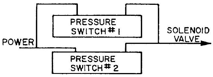 Figure 2-7.-Noncomplex parallel redundancy. (This type of redundancy guards against failure to close when called upon to close.)
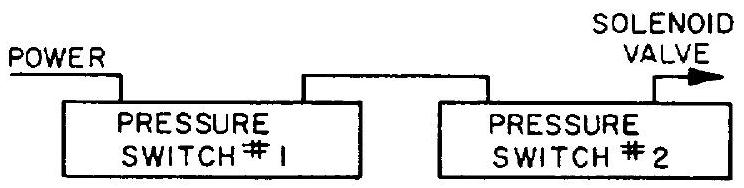 Figure 2-8.-Noncomplex series redundancy. (This type of redundancy guards against inadvertent closing, i.e., closing when not called upon to close.)
Complex Redundancy
The original function carried out by one component. Failure sensors, logic circuits and switching devices energize an identical standby component, when needed. The advantages obtained can be completely offset by the additional complexity of sensing and switching circuitry. The potential problem area may be merely shifted from the equipment to the failure-detection components. However, this standby redundancy may be advantageous when long mission times are involved (e.g., days or weeks) and where it may be undesirable to also subject the backup equipment to prolonged operation.
A typical example is an electric power emergency battery with voltage sensor and switchover circuitry.
Fatigue Failures
Fatigue failures are fractures caused by repeated load applications at stresses considerably lower than those causing failures in a single load application. They are the most common type of mechanical failure. The ability of a part to resist fatigue failure cannot be checked without destroying the part. Checking is possible, however, through destructive endurance tests with representative samples selected at random.
Most fatigue failures start with a crack at or near an outside surface because stresses are apt to be greatest there. The actual failure will result from gradual propagation of these cracks.
The point at which the crack will start will depend upon the geometry of the part and on surface conditions. Any notch or other stress raiser, being a point of highest stress concentration, is a potential starting point for fatigue cracks. Fillet radii that are too small, threads, oil holes, keyways and similar surface irregularities are all potential sources of fatigue failure. Although a part may be designed to be free of geometric irregularities, having no shoulders, grooves or the like, it may still contain a great number of minute stress raisers. These may be tool marks, scratches, identification stamp marks, or various inherent discontinuities in the material itself, such as inclusions of foreign matter and quenching cracks. The design engineer should make every effort to avoid stress concentrations in a highly-stressed part subject to repeated load applications. In the design, rigid specifications should be called out for surface finishes. For repeated load services, forgings are generally preferred to castings. Ductile materials are preferred to material prone to become brittle.
In welded constructions, the joints are subject to almost all types of stress concentration and fatigue failure. Wherever possible, welded joints should be minimized in the design of parts subject to repeated loads. Rigid procedures for welding and inspection must be called out in the design.
Over-Stress and Over-Strain
Stress analysis in mechanical design to prevent over-stress and over-strain will be discussed in section 2-4. The interrelationship of stress and reliability of mechanical parts is illustrated in figure 2-9.
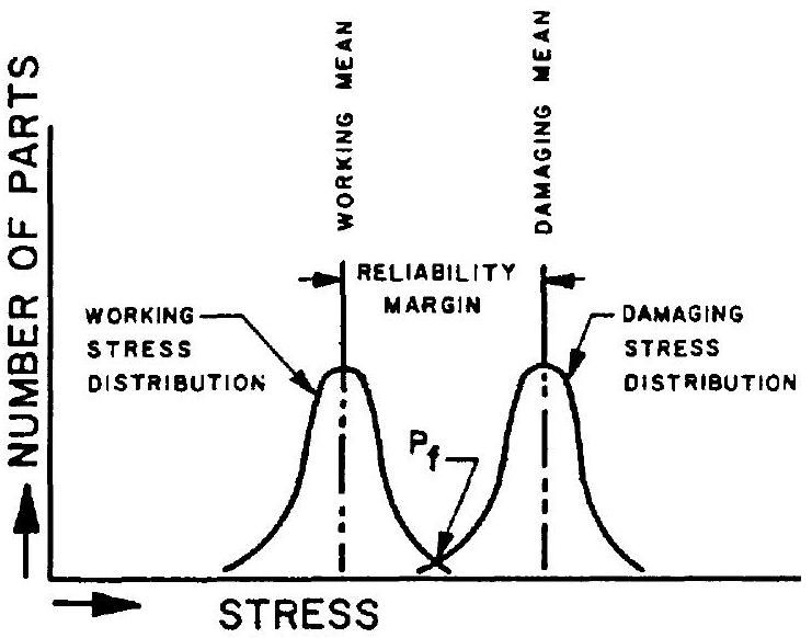 Figure 2-9.-Interrelationship of stress and reliability as related to mechanical parts.
Two stress levels exist for every part in a given engine component: the working stress, and the damaging stress at which failure occurs. The failure may be either a fracture, or a deformation beyond allowable tolerances. Each of the two stresses are mean values of a distribution about a mean. The difference between the working and the damaging stress mean values is indicative of the stress reliability margin of the part.
The deviations from the mean working stress result mainly from variations in the dimensions of the part, and from operational and environmental conditions. The distribution about the mean damaging stress results from variations in material properties, fabrication processes, quality control and maintenance practices. The area , where the two distributions overlap represents the probability of failure, or unreliability.
Close control of functional and environmental loads may decrease the variation of the working stress about the mean. Likewise, better materials and strict quality control should increase the damaging-stress mean value, and decrease the variation about the mean. Thus, the area of overlap may be substantially reduced or eliminated, and reliability increased.
Failures of Combustion Devices
Under steady-state operating conditions, combustion devices in liquid-propellant rocket engines are exposed to hot gases with temperatures ranging from to . The walls of these devices are either made from high-temperature-resisting (refractory) materials, or are provided with effective cooling, through heatabsorbing effects, ablative cooling, propellant film and/or regenerative cooling. Structural failure may occur because of erosion, from wall temperatures exceeding the values assumed during design. Or failure may occur from a combination of excessive temperatures and pressures.
Under certain transient or unstable conditions, such as during engine start or stop, combustion instability or abrupt pressure surges may occur and cause a failure. See chapter IV, "Design of Thrust Chambers and Combustion Devices."
Electrical Failures
Although predominantly an assembly of mechanical parts, a modern rocket engine employs a number of electrical devices without which it cannot function reliably. Among the electrical components used most widely are: power sources (batteries), converters (DC to AC), wires and harnesses, connectors, switches, relays (electromechanical and solid-state), timers, pressure switches, diodes, solenoid valves, servomotors and position indicators.
All of these devices are, to various degrees, potential sources of failure, the consequences of which are just as detrimental as failure of mechanical parts. By proper design and assembly instructions, and by careful selection of the elements, the designer can forestall electrical failures and thus assure overall systems reliability. Most common potential electrical failures which must be prevented are:
Cold solder spots in connectors, wirings and electrical elements. They result in often sporadic discontinuities, particularly under vibration.
Short circuits in wirings, connectors and other electrical devices. This may be due to poor design, leaving insufficient separation between connector pins, lugs and the like; excessive solder; damaged insulation due to poor harness installation, chafing under vibration and poor handling; overload and/or overheating in solenoids; moisture in connectors.
Fused relay contacts, due to overload and/or incorrect current rating of the elements.
Relay and switch contact loss under vibration. This is really an electromechanical malfunction. It can be prevented by proper relay selection, shockmounting, orientation of installation, replacement by solid-state circuitry where possible.
Power failure resulting from one or more of the causes listed above. Prevention means include emergency batteries and overload switches, combined with subcircuit isolation through diodes. A liquid-propellant rocket engine usually includes additional electrical elements as required for instrumentation and telemetry. These may include instrumentation power supplies, end organs (sensors, pickups, thermocouples, accelerometers, position indicators), signal conditioners (analog-to-digital), and wiring. Although, as a rule, instrumentation is not required directly for proper function of the engine system, its failure may indirectly cause engine malfunction, by interference with engine operation. For instance, a pressure pickup may rupture and cause premature depletion of a gas supply; the same event in the fuel system may cause an enginecompartment fire; improper installation of a thermocouple may block a vital lubricant or other line.
The engine designer's task includes engine instrumentation. It is obvious, therefore, that this peripheral system, too, will require his full attention.
Manufacturing and Material Defects
Manufacturing and material defects of engine component parts directly affect the reliability of the components. These defects can be prevented only by strict quality control. The areas of quality control may be subdivided as follows: (1) Materials inspection. The extent of inspection and testing conducted with raw materials depends upon the nature of the part for which they will be used. Inspection of materials includes testing of their composition, uniformity, mechani- cal properties, fabrication and heattreating characteristics, and possibly of other properties as the application may demand. (2) Traceability. By the time a materials defect is detected, many more parts may have been made from the same lot or batch of raw material. If accurate records have been kept, for what parts which numbered material lots have been used, it will be possible, without a "panic," to withdraw and replace all parts made from the faulty lot. The importance of accurate and complete records is obvious. (3) Process inspection. This refers to all shop inspections made of the parts as they are being processed. Its purpose is to check the performance of the operators and tools or equipment, and to sort out faulty parts as soon as errors are detected. (4) Salvage. This includes the decision whether defective materials or parts can be corrected or will be scrapped. (5) Final inspection. This is the inspection of the completed component parts to insure they are within the limits required by the design. (6) Checking of actual service performance. This includes investigation of complaints and studies of actual service performance of the part in the engine system (see "Failure Reporting System").
Unexplained Failures
From time to time failures occur which cannot readily be isolated as having originated in a given component or part. This may be because several causes were present simultaneously and could not be separated. Or instrumentation was inadequate, recording only the ultimate effects but not the cause. Or that an incomplete investigation was conducted, maybe in the hope it would not happen again.
Classification of a failure as "unexplained" should never be done as a matter of convenience, but only as a last resort if the most thorough investigation did not establish a clear cause. Complete and accurate records must be kept of the details associated with the failure. Through special statistical methods it may be possible to isolate the cause or causes at a later date. Also, special instrumentation may immediately be added in the areas of suspected but unproven causes. But the most sophisticated explanation of a failure cannot transform it into a success.
Human Error
Experience with early manned rocket flights has shown that certain functions could be performed better by trained men than by automatic devices. It appears certain that future spaceflight efforts will continue to employ combinations of automatic and manual systems, the ratio of the two depending on mission requirements. Even in those missions which are unmanned and therefore appear to be fully automatic, man is still directly involved: during launch preparations, and through postlaunch commands for trajectory-correction maneuvers, information playback, and similar actions.
We must realistically recognize that even a fully-trained, and very alert individual is subject to error. He may commit an error at a desk while using a slide rule, or while connecting a number of hydraulic lines, or under stress while pushing buttons. The history of rocketry is full of glaring examples. Whenever it happens, the most eloquent regrets are probably voiced by the designers of the system involved: if someone had not done something to their perfect creation, it would have worked faultlessly. The reaction is understandable, but wrong.
For whatever reason a system failed, it obviously was not perfect. Its designer did not consider human nature, nonideal operating conditions, nor emergency situations. Clear and complete drawings, specifications and other written instructions are important but they will not prevent, by themselves, human errors, because they can be misplaced, misread, or not read at all.
It is not surprising that the elimination of human error, or more positively, the perfection of the integration of man with the machine, is becoming an independent branch of engineering. It would be beyond the scope of this book to go into the details of "Human Engineering" or "Human Factors Analysis." Simply by applying mostly known methods and common sense, the rocket-engine designer can do much to prevent human error by the design of his parts and by mandatory actions during their building, checking and handling. The following are only typical examples of a probably infinite number of possibilities of preventing human error by design.
Clear marking of bolts, lines, connectors, wires, etc.
Use of dissimilar connectors, dissimilar threads, a variety of keyways, and the like, to make incorrect electrical and mechanical connections impossible.
Safety wiring; electrical and mechanical interlocks.
Painting bright red, and/or attaching bright red streamers to, auxiliary devices which must be removed before operation.
Storing of components and systems which have successfully passed all inspections and checkouts, in locked rooms requiring two different keys from two different individuals.
Intentional attempts at improper handling, assembly, checkout and operation of components and systems, to assist "foolproofing," during development. None of these and numerous similar steps will eliminate human errors completely. However, they will substantially reduce their possibility and thus contribute to overall reliability.
Design Reviews for Reliability
The reliability of rocket engines and their components depends on many factors. Design reviews are among the most potent methods for increasing reliability. In practice, a design review is the progressive evaluation of a design. It starts with the preliminary schematics, layouts and specifications and extends through the release of all final drawings. Those conducting reliability design reviews should include: reliability specialists, design engineers, development, test and service engineers, and various specialists for structures, materials, manufacturing, and quality control.
A minimum of three design reviews is recommended for each design:
Preliminary design review.-This is preliminary review of work statements, basic concepts, schematics, layouts, and analyses.
It determines development needs and results in decisions for the next design phases. This review should uncover misapplications, critical areas and marginal designs at an early stage, when changes can be effected without difficulty.
Critical design review.-This is the most important review for decisions and approvals. It includes formal review of all reliability aspects of layouts, analyses, planned development tests and procurement specifications.
Final design review.-This is the final review of overall design layouts, detail and assembly drawings, analyses, process specifications, and R&D test results, before production release. The reviews should emphasize: (1) Structural integrity (2) Function and performance (3) Customer (vehicle) connections and envelope (4) Materials compatibility and component interfaces (5) Produceability and cost (6) Reliability and repeatability: malfunction effects (7) Environment and servicing (8) Special requirements
It is highly recommended that the agreed-to layout bear the approval signatures of the groups involved.
A reliability checklist tailored to the individual designs may be used as a guide during the various design review phases. The "Design Check-Off Sheet" shown in section 2-2 may be used for this purpose.
Design reviews are valuable and cost-saving tools for improving reliability. A well organized and staffed review group will assure a meaningful review and instigate effective recommendations and actions. Complete documentation of all review details will provide valuable data for future reference.
Under "Manrating" the cost of a single launch was mentioned. Press releases give the cost of a major space program as about 3.5 billion dollars a year-10 millions a day! To save a mission, or just a single day of preparation, by improved reliability, quite clearly, is worth the effort.
Likewise, the loss of a launch, or a day in the program, is very costly indeed. The rocketengine design can contribute substantially to prevent it.
Cost
Cost considerations should enter a design at the very beginning. Not only from the viewpoint of competitive bidding and narrow profit margins but of available and/or developed national resources as well. A major rocket vehicle program quite possibly may tax the resources of certain materials, facilities, and services to the limit. Moreover, it should be ascertained that the program does not rely on facilities, and on supply of materials and of propellants that may not become available for several years. The rocket engine under design may well be for a project costing a total of hundreds of millions of dollars. Savings of even fractions of a percent can therefore amount to millions of dollars.
Cost, as far as the designer is concerned, will be affected by the selection of materials; by the machinery required to make the parts; by the time and skill required to make them; by the difficulty of assembling, testing, and servicing the parts; and last, but not least, by the experience of the people making the design.
Availability (Scheduling)
The best design, the most perfect device, may be useless if it is not available when needed. In a way, the design of (in our case) a rocket engine is a product by itself. It must be planned, prepared, and made. It results in physical products: drawings, written instructions, and procedures. which all must be faultless and available when needed. Delays in the release of drawings can become very costly indeed. In a manufacturer's overall plan of action, the design will be timed and synchronized with other activities. If the drawings are not available on schedule, sizable portions of a machine shop or an assembly plant may be forced to stand idle.